Structural Engineer Brief

Bridge House, Unit 1, 26 Ducie Street, Manchester. Cat B office fitout requiring structural works to existing concrete-frame building.

1. Existing Building

Two-storey commercial building. Ground Floor and Lower Ground Floor connected by an existing metal staircase at the rear (north). This is a lightweight steel staircase that can be unbolted and removed. The slab opening will be infilled. The existing south entrance has concrete steps that require careful demolition. New vertical circulation (staircase and DDA lift) will be formed at the front (south) of the building.

Existing Staircase (To Be Removed)

location

North (rear) of building

type

Metal staircase. Lightweight steel construction, bolted to slab. Simple removal.

serves

Ground Floor to Lower Ground Floor

opening size

3000mm x 4000mm

reference drawings

The Green, MLP Design. GF: 1171-FP-01 Rev A (1:200 @ A4). LGF: 1170-FP-01 Rev A (1:200 @ A4). Both dated 11/06/2019.

construction

Steel/metal frame. No embedded reinforcement in staircase itself. Bolted connections to existing concrete slab at GF and LGF levels.

action

Unbolt and remove metal staircase. Infill slab opening with RC slab to match surrounding floor level.

Key Dimensions

Existing stairwell room (GF)

~4900mm x 5170mm (264 sqft)

Existing stairwell room (LGF)

~5700mm x 4690mm (261 sqft)

Existing staircase opening

3000mm x 4000mm

Total rise LGF to GF

4725mm

LGF to Street Level

3675mm

Street Level to GF

1050mm

2. Scope of Structural Works

Sequence: survey existing structure, remove rear metal staircase (unbolt), install temporary propping, demolish concrete south entrance steps, infill rear slab opening, cut new openings at front, install edge trimmers, excavate lift pit. All to SE design.

New Slab Openings Required

Combined stairwell opening (GF slab)CRITICAL
Inner (clear)

2400mm (W) x 4200mm (D)

Outer (incl walls)

2700mm x 4500mm (including 150mm enclosure walls)

One combined opening. The GF straight flight (6R, 1200mm x 1500mm) sits within the LGF stairwell void above the LGF dog-leg below. No separate GF opening needed.

Lift shaft opening (GF slab)CRITICAL
Inner (clear)

1500mm (W) x 1700mm (D)

Outer (incl walls)

1800mm x 2000mm (including 150mm shaft walls)

Separate opening adjacent to stairwell. Full height from LGF pit to GF headroom zone.

Lift pit excavation (below LGF slab)CRITICAL
Inner (clear)

1500mm x 1700mm x 1100mm deep

Outer (incl walls)

1800mm x 2000mm external (pit walls)

Below LGF slab level. Waterproof tanking required. Sump pump if below water table. Base slab to SE design.

01Remove existing concrete entrance steps and make good
Scope: Remove existing concrete stepped entrance structure at street level and dispose off-site. All associated finishes, balustrades, and step nosings to be removed. Make good surrounding surfaces, thresholds, and floor finishes to form new level entrance lobby.
Method: Concrete entrance steps require careful demolition (diamond saw cutting or breaking out). Temporary propping may be required. Avoid damage to surrounding structure. Infill and level as required. Floor finish to match new entrance lobby specification.
Notes: The south entrance steps are concrete construction. This is the heavier demolition item. Required to form new entrance lobby at street level. Allowance item. Exact scope to be confirmed on site.
02Form openings in existing concrete slab for new staircase and lift
Scope: Allowance to form openings in existing concrete slab as indicated to facilitate new staircase and lift works. Combined stairwell opening: 2400mm x 4200mm. Lift shaft opening: 1500mm x 1700mm. Both through GF slab.
Method: Diamond saw cutting. Temporary propping below during cutting. Edge beams or trimmer steel to SE design. Cover meter survey to identify existing reinforcement before cutting.
Notes: Provisional item. Final opening sizes and positions subject to SE design and lift manufacturer builder's work drawings. See slab openings detail below.
03Existing rear metal staircase removal
Scope: Unbolt and remove existing metal staircase at the rear (north) of the building. Dispose off-site. Fill slab opening with reinforced concrete slab to match surrounding floor level. Includes formwork, rebar, and concrete pour for infill slab.
Method: Unbolt metal staircase connections at GF and LGF slab levels. Crane or manual removal of steel sections. Temporary propping to SE design for slab opening. Form and pour RC infill slab with dowel bar connections to existing structure.
Notes: Size: 3000mm x 4000mm opening. Rear of property. The staircase itself is metal and easily removed. The main structural work is the RC infill slab to close the opening. Structural engineer sign-off required for infill design.
04New staircase and lift openings — Front of property
Scope: Form new openings in existing concrete slab at the front of the property to facilitate new staircase and passenger lift. Stairwell opening: 2400mm x 4200mm. Lift shaft opening: 1500mm x 1700mm. Includes diamond saw cutting, temporary propping, and edge trimming to both openings.
Method: Cover meter survey to identify existing reinforcement before cutting. Diamond saw cutting. Temporary propping below during cutting. Edge beams or trimmer steel to SE design.
Notes: Stairwell opening: 2400mm x 4200mm. Lift shaft opening: 1500mm x 1700mm. Front of property. Structural engineer sign-off required. Lift shaft to coordinate with manufacturer builder's work drawings.
05Excavate and form lift pit below LGF slab
Scope: Allowance to break out LGF slab and excavate new lift pit: 1500mm x 1700mm clear, 1100mm deep below LGF slab level. Form reinforced concrete pit base slab and pit walls. Waterproof tanking to all faces. Dispose of excavated material off-site.
Method: Break out LGF slab locally. Excavate to required depth. Tanking membrane to external faces. Form pit with waterproof concrete (base slab and walls). Sump pump connection if groundwater present.
Notes: Ground conditions to be confirmed before excavation. Pit dimensions to be coordinated with lift manufacturer builder's work drawings. Allowance item.
06Edge trimming and support
Scope: All new slab openings to have reinforced edges. Trimmer beams or steel angles to support cut slab edges and transfer loads around openings.
Method: Steel trimmers bolted or welded to existing structure. Pad stones where bearing on masonry. Connection details to SE design.
Notes: Critical for maintaining structural integrity of floor slabs after large openings formed.

3. Position Structural Zones

Drag zones to position. Click a zone in the legend to edit its dimensions.

Ground floor plan

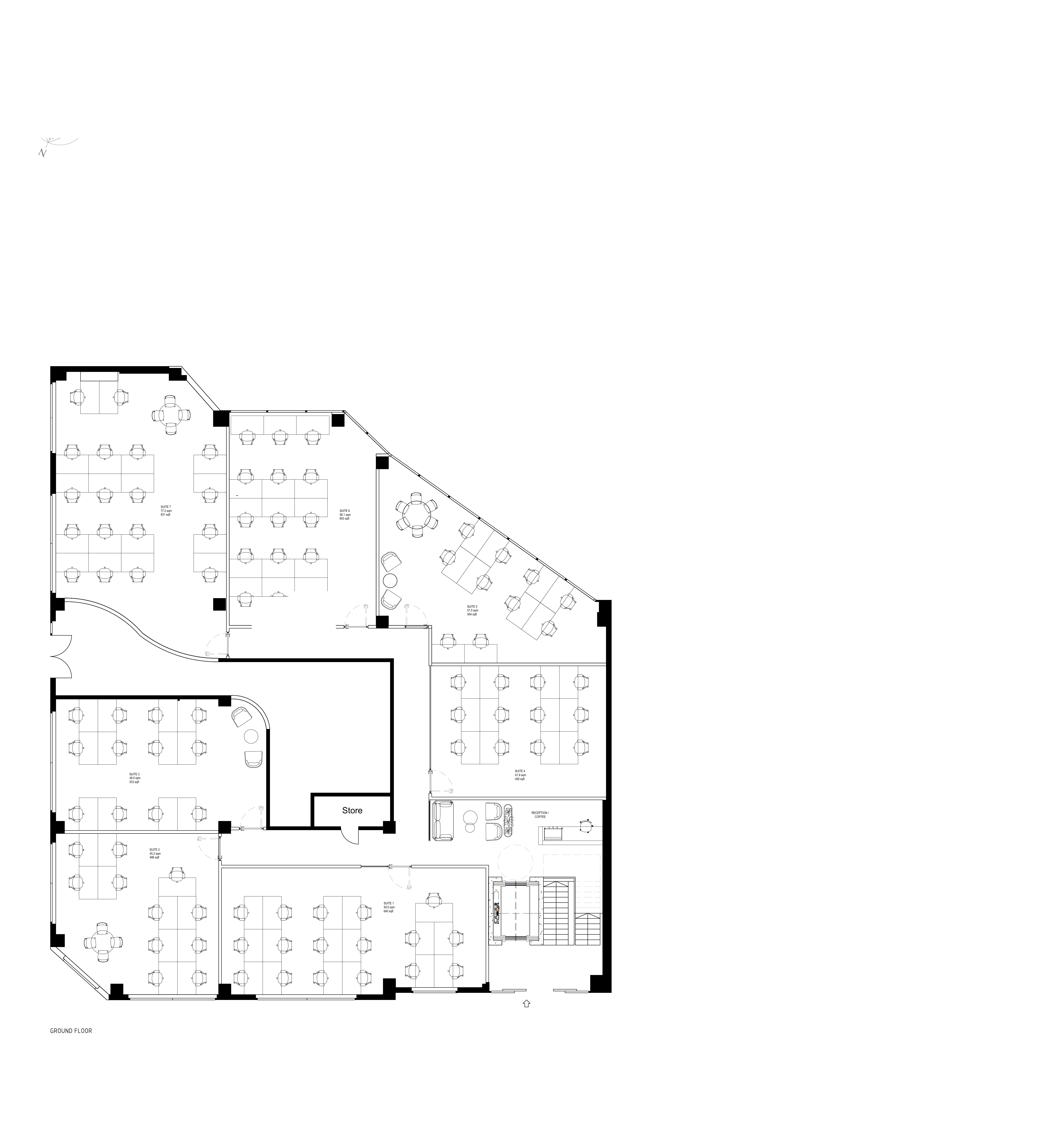
4. Position Structural Zones on MLP Plans

Drag zones to position. Click a zone to edit dimensions. Hide zones per floor without affecting the other.

MLP Ground Floor Plan

5. Building Measurements & Structural Dimensions

All measurements drawn on MLP Design floor plans. Toggle layers to show/hide perimeter walls, columns, and column grid spans. Zone dimensions from the placer above are the source of truth. All dimensions to be verified on site.

MLP Ground Floor — Dimensioned
Perimeter wall dimensions (mm)
Column grid spans (mm)
Structural columns (annotated WxH mm)

All dimensions measured from MLP Design floor plans (1:200 @ A4, 600 DPI, calibrated at 118.75 px/m). Column sizes approximate from plan. All dimensions in mm. Verify on site before works commence.

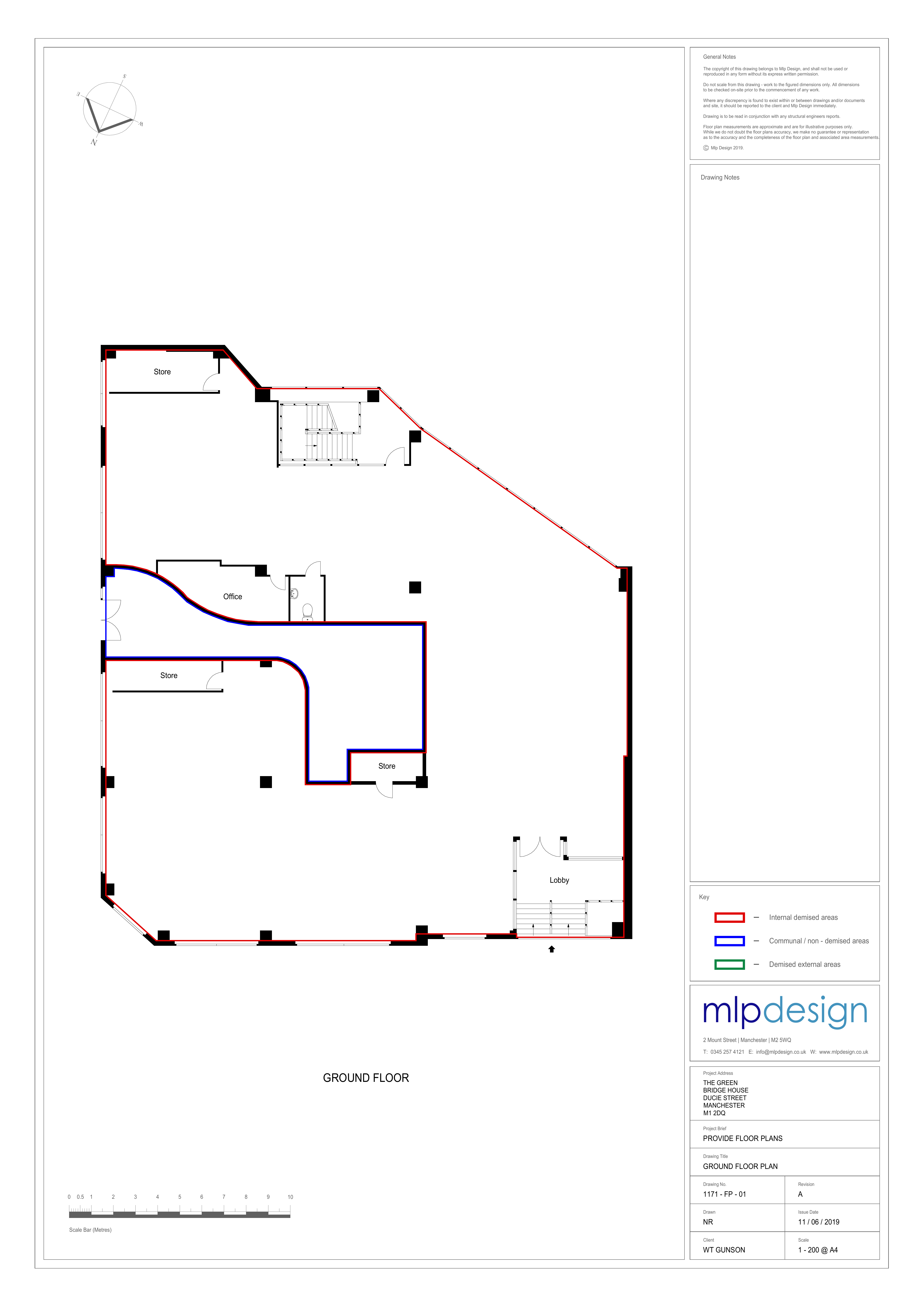
6. Structural Works Plans

New works overlaid on the existing Ground Floor plan. 1:50 at A1. Red = demolition. Blue = new stairwell. Green = new lift shaft.

Builder's Works Plan (All Structural Works)

Builder's Works Plan showing all structural works on existing GF plan

Staircase Works Plan

Staircase works plan

Lift Works Plan

Lift works plan

7. New Staircase Specification

New staircase at front (south) of building. Three flights serving LGF, Street Level, and GF.

configuration

LGF: U-shaped dog-leg. GF: straight flight. Both share street-level landing.

lgf dog leg

Flight 1a (west, 12R heading north) + intermediate landing + flight 1b (east, 9R heading south). Open well between flights.

gf flight

Straight flight, 6 risers from street level landing up to GF, heading north.

riser

175mm (Part K max 220mm)

going

250mm (Part K min 220mm)

two r plus g

600mm (target 550-700mm)

clear width

1200mm between handrails (Part K min 1000mm)

headroom

2000mm minimum (Part K)

total rise lgf sl

3675mm (21 risers x 175mm)

total rise sl gf

1050mm (6 risers x 175mm)

total rise

4725mm (LGF to GF)

construction

Steel or reinforced concrete

handrails

Both sides, 950mm height, brushed steel or brushed gold. Continuous across landings.

treads

Polished concrete to match screed, or steel plate with anti-slip nosings

nosings

Contrasting anti-slip nosings to all treads (Part M / Part K)

fire doors

FD30S self-closing fire doors at each level, 900mm clear opening

lighting

Maintained emergency lighting per Part B and BS 5266

stairwell inner

2400mm (W) x 4200mm (D)

stairwell outer

2700mm (W) x 4500mm (D) including 150mm enclosure walls

6. DDA Passenger Lift

New passenger lift adjacent to stairwell at front (south) of building. Three stops.

manufacturer

Schindler 3100 MRL (or equivalent)

type

Machine Room-Less passenger lift

capacity

400kg / 5-person

speed

1.0 m/s

floors

2 (LGF and GF). Street level is intermediate stop.

stops

3 (Lower Ground Floor, Street Level, Ground Floor)

travel

4725mm total. LGF to Street: 3675mm. Street to GF: 1050mm.

car

1100mm x 1400mm internal (DDA minimum)

doors

Automatic sliding, stainless steel finish, 900mm clear opening

configuration

LGF and Street Level doors open south. GF door opens north (into building). Through-car at GF only.

power

3-phase 400V, 16A isolator, TPN MCB in main distribution board

compliance

EN 81-20, EN 81-50, Equality Act 2010, Part M

features

LED car lighting, ARD battery lowering, emergency intercom, overload sensor

Shaft Requirements

construction

Blockwork or reinforced concrete walls, minimum 1-hour fire rating

shaft internal

1500mm x 1700mm internal. 150mm wall thickness.

shaft overall

1800mm x 2000mm overall (including walls)

height

Full height from LGF pit through street level to GF

pit

1100mm depth. Waterproof tanking required. Sump pump if below water table.

headroom

3400mm above top landing (GF). Per EN 81-20.

ventilation

Shaft ventilation per Part B and EN 81-20

builder work

Builder's work drawings required from lift manufacturer before construction

7. Required SE Deliverables

Structural engineering calculations, designs, and sign-offs required before site works can commence. All deliverables to be provided before Week 1 site start.

SE-001Structural survey of existing buildingCRITICAL PATH

Survey existing slab openings (rear metal staircase opening, south entrance) and surrounding structure. Confirm slab thickness, reinforcement details, and condition. Identify load paths affected by works.

Required
SE-002Temporary works design (propping)CRITICAL PATH

Propping design for slab openings and concrete entrance demolition. Method statement for safe removal sequence. Propping positions, loads, and duration. Note: rear staircase is metal (simple unbolt), but slab opening infill requires propping.

Required
SE-003Infill slab and entrance demolition calculationsCRITICAL PATH

Calculations for rear slab opening infill (300mm RC, dowel connections), concrete south entrance step demolition, and load transfer during works.

Required
SE-004New GF slab opening: stairwell (2400mm x 4200mm)CRITICAL PATH

Design for forming combined stairwell opening in GF slab. Edge trimming, trimmer beams, reinforcement around opening. This single opening serves both the LGF dog-leg and GF straight flight.

Required
SE-005New GF slab opening: lift shaft (1500mm x 1700mm)CRITICAL PATH

Design for forming lift shaft opening in GF slab adjacent to stairwell. Edge trimming, trimmer beams. Coordinate with lift manufacturer builder's work drawings.

Required
SE-006Lift pit design (1100mm deep below LGF)CRITICAL PATH

Reinforced concrete pit below LGF slab. Base slab, pit walls, waterproof tanking specification. Ground investigation may be required.

Required
SE-007Lift shaft structural designCRITICAL PATH

New shaft walls (blockwork or RC), 150mm thick, 1-hour fire rating. Full height from pit to GF headroom zone. Shaft to support guide rail loads.

Required
SE-008New stairwell structural designCRITICAL PATH

U-shaped dog-leg stairwell: steel or RC flights, intermediate landing at half-height, connection to existing structure. Enclosure walls 150mm, fire rated.

Required
SE-009Steelwork connection details

Connection details for new steel to existing structure. Pad stones, base plates, bolt specifications. New-to-existing interface details.

Required
SE-010Additional openings and lintels

Calculations for any other new openings through existing concrete/masonry structure. Lintel schedules where required.

Required

8. Programme

Indicative structural works programme. SE deliverables must be complete before Week 1.

Structural survey of existing staircaseBefore Wk 1. Required before any works.
SE calculations and propping designBefore Wk 1. All SE deliverables must be received before site start.
Remove rear metal staircase + demolish concrete south entranceWk 1 (3 days). Unbolt metal staircase. Break out concrete entrance steps.
Making good (infill rear slab opening + entrance)Wk 1-2 (5 days). Pour RC infill slab at rear. Make good entrance level.
Cut new slab openings (stairwell + lift)Wk 3-4 (5 days). Diamond cutting, edge trimming.
Lift pit excavation and formationWk 4-5 (5 days). Below LGF slab. Tanking.
Lift shaft constructionWk 5-7 (10 days). Blockwork or RC walls.
New stairwell constructionWk 5-7 (10 days). Parallel with lift shaft.
Lift installation and commissioningWk 8-10 (15 days). After shaft complete.
Stairwell finishes (treads, handrails, fire doors)Wk 8-9 (5 days). After stairwell structure complete.

SE calculations, propping design, and lift manufacturer builder's work drawings must all be received before Wk 1 site start. Asbestos survey required before demolition. Note: rear staircase is metal (simple unbolt and remove). South entrance steps are concrete (require breaking out).

9. Download Packs

Structural Engineer Pack

Complete pack for SE quotation. Includes the brief PDF (9 pages covering project overview, existing building, scope of works, slab openings, staircase and lift specifications, SE deliverables, programme, and information outstanding), plus all supporting drawings and existing building plans.

01 Existing Plans

MLP Design GF + LGF (1:200)

02 Testfit Plans

Incognito Stage 1 (1:100)

03 GA Plans

GF + LGF (PDF/SVG/DXF)

04 Staircase Drawings

Section, plan, schedule

05 Lift Drawings

Section, plan, schedule

06 Structural Works

Stair, lift, builder plans on GF

07 Builder's Works

Full scope, specs, dimensions

08 Key Dimensions

All openings, heights, sizes

Staircase Tender Pack

Drawing pack for staircase contractor quotation. Developed section, plan views, specification schedule, and structural works plan.

Structural Works Plan

1:50. New stairwell on existing GF plan. Opening dimensioned.

Section (Developed)

1:20. All three flights with break marks at direction changes.

Plans + Specification

1:25 plan views. Full spec: flights, demolition, fire, regs.

Builder's Works Pack

Full scope of works for builder quotation. Includes structural works plan showing all zones on existing floor plan.

Structural Works Plan

1:50. All works on GF plan: demolition (red), stairwell (blue), lift (green).

Scope Document

Demolition, making good, slab openings, lift pit, all specs.

Key Dimensions

All opening sizes, floor heights, staircase and lift dimensions.

Lift Company Tender Pack

Drawing pack for lift company quotation. Shaft section, shaft plans, specification schedule, and structural works plan.

Structural Works Plan

1:50. Lift shaft on existing GF plan. Shaft, car, pit dimensioned.

Shaft Section + Plans

1:20. Pit, floor levels, headroom, doors, car outline, walls.

Specification Schedule

Full spec: general, shaft, car, doors, electrical, programme.